
![]()
Power Generation Operation And Control 3rd Edition Solution Manual Pdf ~upd~ Official
dC1dP1=dC2dP2=λthe fraction with numerator d cap C sub 1 and denominator d cap P sub 1 end-fraction equals the fraction with numerator d cap C sub 2 and denominator d cap P sub 2 end-fraction equals lambda
It provides solutions for understanding automatic generation control (AGC), load frequency control (LFC), and how power systems handle sudden changes in demand or unit outages. 4. Transmission Constraints and Optimal Power Flow (OPF)
This article explores the structure of the textbook, the role of solution manuals in mastering the material, and how to approach complex power systems problems effectively. Overview of the Textbook
This comprehensive guide explores the core concepts covered in the third edition, the value of structural solutions, and how to effectively utilize academic resources to master power system analysis. Understanding the Scope of the Third Edition
Utilize GitHub repositories where engineering students have shared verified Python or MATLAB code for the textbook's specific algorithms. dC1dP1=dC2dP2=λthe fraction with numerator d cap C sub
Finding reliable resources for advanced power systems engineering can be challenging. Power Generation, Operation, and Control (3rd Edition) by Allen J. Wood, Bruce F. Wollenberg, and Gerald B. Sheblé is a foundational textbook for electrical engineering students and professionals.
user wants a long article for the keyword "power generation operation and control 3rd edition solution manual pdf". This likely refers to the textbook "Power Generation, Operation, and Control" by Allen J. Wood, Bruce F. Wollenberg, and Gerald B. Sheblé. The user likely wants an article that provides an overview of the solution manual, its contents, where to find it, and perhaps some context. I need to search for relevant information. I'll follow the search plan. search results show various pages. I need to open some of them to get more details. The user's question has high authority requirements, I should prioritize using authoritative sources to ensure the article's credibility. I'll open result 0 from the first search, result 0 from the second search, result 1 from the second search, result 0 from the third search, result 1 from the third search, result 4 from the fourth search, and result 1 from the sixth search. search results provide some information. I also see a Google Groups link that might contain a solution manual. I'll open that too. Google Groups page is very long and contains a list of solution manuals. I need to find the specific one. I'll search for "power generation" within the page. page seems to be a list of solution manuals. It might include the one for this textbook. I'll scroll further down.'s a long list, but the specific entry might be around line 3. I already saw it. The page seems to be a collection of solution manuals offered for sale or trade. I should look for other sources like GitHub. also need to search for "Power Generation Operation and Control 3rd edition solution manual pdf" on GitHub. seems there are no direct matches on GitHub. I'll also search for "Power Generation Operation and Control" PDF.'ll also search for "Power Generation Operation and Control 3rd edition solution manual pdf free". also need to search for "Power Generation, Operation, and Control 3rd edition solution manual pdf" on Google Books. user's question is likely looking for a PDF of the solution manual. I should provide context about the book and its solution manual, including information on where to find it, how to access it legally, and the contents. I'll structure the article with an introduction, sections on what the solution manual is, where to find it, what it contains, its importance, and a conclusion. I'll cite sources like the University of Minnesota page (source 7) for information on the solution manual and the solution manual page (source 1) for details. I'll also mention the Google Groups listing (source 9) as an example. I'll include information about the book's ISBN, authors, and publication date. I'll also mention the legal and ethical considerations. article provides a detailed guide to the solution manual for the 3rd edition of "Power Generation, Operation, and Control," a cornerstone text in the field. It clarifies what the manual is, where it can be found, and its invaluable role for both students and professionals in electrical and power systems engineering.
For further exploration of these topics, additional academic resources are available that provide: In-depth summaries of specific chapters.
Often, university engineering libraries provide access to instructor solution manuals. Overview of the Textbook This comprehensive guide explores
Wiley (the publisher) often provides resources for educators who adopt the text. Important Considerations
When seeking these materials, it is important to access them through legitimate academic channels. Using authorized resources ensures that the information is accurate, up-to-date, and respects the intellectual property rights of the authors and publishers. For students, the most reliable path to accessing these tools is through university-provided instructor resources or library portals.
Contingency selection methods and power system stability analysis. Market Operations:
Insights into Automatic Generation Control (AGC) and how systems maintain frequency stability. Key Topics Covered Power Generation, Operation, and Control (3rd Edition) by
Using a solution manual as a direct copy-paste source for homework assignments violates institutional academic integrity policies. It strips away the cognitive effort required to understand grid control mechanics. Use the guide strictly as an unblocking tool when stuck on a specific optimization problem.
: Mathematical formulations for security-constrained dispatch. Market Operations
This guide outlines how to access available solutions and key topics covered in the manual. 1. Official and Authorized Access
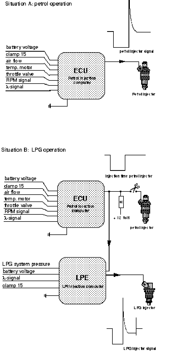
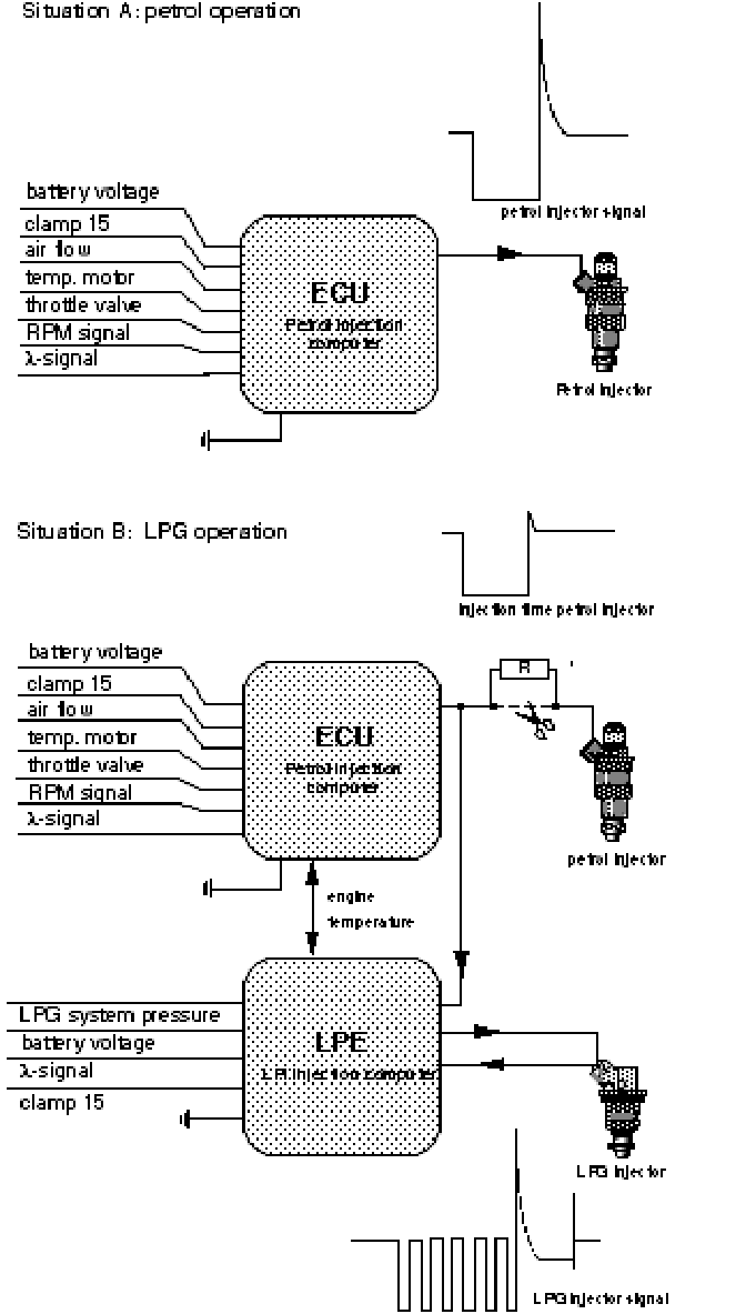
The LPE unit
The LPE unit is the electronic control unit of the system. This unit consists of the following components:
• A motherboard on which the universal electronic systems are placed.
• A module board with the more specific electronics, e.g. for a deviating l-probe.
The LPE is always provided with the basic software, which is complemented with the brand/model-specific engine data.
The unit has a splash proof 35-pin connector which allows mounting under the hood. In some cases a separate power module is used for control of the injectors. This power module is mounted in a similar housing.

The injector characteristic
The main task of the LPE is to calculate the LPG injection time and to control the injectors or the power module (when there is an external power module)
The injector control is earth-switching. The negative side of the injector is connected to the earth.
Opening the injector against the high system pressure (bottom-feed injector) requires a considerable current. Because we have a constant supply voltage, a high opening current can be achieved by using a low-impedance injector.
Injector impedance formula
This current is sufficiently high to open the injector against the system pressure and the spring tension. After these forces have been overcome, however, a hold current of +/- 1.5A is all that is required to keep the injector open. If we did not reduce the current after the injector is open, the coil would overheat and burn through. To produce this lower hold current, we employ the following 2 methods:
• Control strategy up to and including LPE 4
When the injector has been opened with a current of +/- 7A, a series resistor will be connected to reduce the hold current to the required +/- 1.5 A. The hold current remains at this value until the injector is closed.(fig.32)

• Control strategy beyond LPE 5
. From LPE 5 and higher, the principle of switching the current off and then on after the injector has opened is used. This enables the regulation of the current. The advantage of this method is that less heat dissipation occurs at the driver.(fig.34).
The peaks seen on the oscilloscope screen are caused by the induction of the injector coil.

Injector signal processing
The petrol control unit determines the on-time of the petrol injectors after calculating a large number of variables. This injector signal is an ideal basis for the calculation of the LPG injector on-time.
The injector signal is tapped from the interrupted control wire on the petrol computer side. Because during LPG operation a resistance is connected to it instead of an injector (coil), there is no induction peak.
The incoming signal is converted by the LPE into an injector on-time for the LPG injectors.
Beyond the LPE4 there is a possibility to connect a wire with the engine temperature sensor (coolant). This option is being used to manipulate the temperature during the warm up phase. In this case the petrol ECU calculates a shorter petrol injection time. This way we are given the opportunity to switch to LPG faster after a cold start.
The engine-running safety
The LPi system does not apply a specific engine-running safety as such. That would require taking up the RPM signal of the BDP transmitter or the ignition as a sign that the engine is running.
The petrol system is already provided with an engine-running safety, and this is also used for the LPi system.
This original safety is used on either the injector supply or the petrol pump supply.
By using the power supply in question for the LPE as well as for the drivers, the engine-running safety is also active for the LPi system.
Injector signal processing LPE 5
Injector signal processing with a serial simulation resistance.
The injector signal is tapped from interrupted control wire on the same principle like we used before.
Normally we'll use serial placed simulation resistance's in combination with the LPE 5. This new principle is used to avoid injector faults on the moment that the relays are switching. The petrol injection system is charged on the normal way like when it's running on petrol.
The incoming signal is converted in the LPE 5 into a LPG-injector signal with the strategy like we can see on page 21.
In the next figure we see a feed-back wire from the LPG-injector supply to the LPE pin 14. The LPE 5 has an integrated power-module which is sending out a hold current by switching the current on and off. At every switch-off, a peak voltage is generated. The energy from these peaks may be an interference source for the other electric circuits in the LPE. To avoid these problems an idling circuit is placed over the LPG-injector coil. With this circuit we:
• Extinguish the peak;
• Recycle the peak energy.

Recycling the peak energy is shown in fig. 37. When the LPG-injector signal is being switched off, S1 is opened. The current will no longer flow from battery to the LPE. But it will flow, after it has passed the LPG-injector, through the idling circuit (S2 is closed when S1 is opened) and back to the battery.
Because the voltage of the peak is higher than the voltage of the battery, the LPG-injector will remain open. Even as the LPE does not activate the injector anymore. Before the LPG-injector closes mechanically the LPE has closed S1 so
The injector off-set
The opening and shutting of the injector is a mechanical reaction to an electric signal. The injection needle has a certain mass inertia through which a reaction time is necessary to lift and close the needle.
On opening as well as shutting, the needle lags on the electric control. This lagging can be divided into response lag and close lag, which together determine the difference between activation time and injection time.
The difference between electrical activation time and mechanical injection time is called injector off set.
For the exact dose of fuel, the off set needs to be known.
The response lag depends on both the battery voltage and the fuel pressure. In figure 39 the off set depending on the battery voltage and pressure is shown.
The close lag only depends on the spring pressure behind the injector needle and therefore it doesn't change. On calculating the injection time, the LPE takes variable signals, such as battery voltage and LPG pressure into account.
When the battery voltage is lower, the response lag is higher, and so the injector production is lower. This means the electrical activating time must be extended to get the same output. Furthermore, a higher LPG pressure, for example, leads to a higher LPG output and therefore, the activating time may be shorter. But the higher pressure increases the response time which leads to lower output, which in turn leads to a longer activating time. Figure 39 shows the injector off set.

1 Electrical pulse (LPE 5)
2 Injector response
3 Pulse time
4 Mechanical injection
The fuel selector switch
The fuel selector switch is a touch control that has already been used for quite some time in the AMS LPG system. The fuel selection is indicated by a two-colour LED; red is petrol, green means LPG.
Ams style fuel selector switch schematic
After starting on petrol the LED blinks green-off, while waiting for the switching moment. The same happens when switching from petrol to LPG while driving. In this stage the engine always runs on petrol.
The LED is connected between the green and brown wire of the switch. The touch control contact is made by connecting the white and the yellow wire.
The switch with tank read-out
Beyond LPE 4 the wiring loom makes it possible to make use of the switch with tank read-out. The advantages of this new switch with tank read-out are:
• One less breaker needs to be installed: the breaker in the wire of the petrol level gauge.
• The petrol level can be read, even when the car is in LPG operation.
• The problem of reading from the original gauge no longer exists, even when a heavily damped petrol gauge is fitted.
The injector shut-off unit
The petrol injectors are shut off when driving on LPG.
The shut-off unit consists of two relays that are earth-controlled in the LPE. The other side of the coil receives a constant 12 Volt supply.
When the injectors are shut off, a compensating resistance or replacement coil is connected to the petrol computer. This compensating signal is necessary to prevent a disruption of, or an error diagnosis in the petrol system. In later generations of breaker relays, the compensating resistors are positioned such that when in LPG operation, they are fed by the original injector power supply. This is to prevent certain problems when switching over (see technical specifications). In case of a four cylinder engine, a 4-group relay is employed. For 6 cylinder engines, a 6-group relay is employed.
Petrol start and switching time from petrol to LPG
All LPi cars start on petrol. After starting, the engine will run on petrol for some time prior to switching to LPG.
Starting point of the LPi system is the conversion of the petrol injection time to an LPG injection time. The result is that injection takes place according to all values calculated by the original petrol computer, modified for the LPG fuel.
This strategy applies to all operating conditions, including the cold start. When the petrol computer during idling applies mixture enrichment, this enrichment mainly depends on the temperature.
The main arguments for enrichment are the increased friction resistance and fuel deposition on the cold cylinder wall and the valves. The latter argument does not apply for LPG, because the low boiling point ensures effective evaporation, even at low temperatures. Therefore, the injected LPG quantity is too high, which may cause the engine to stall. Consequently, the switching moment has been made depend on three factors:
• The LPE surroundings temperature
• The engine temperature
• The signal from the l sensor
The LPE surroundings temperature
Beyond software version 205908 the outside air temperature (at the LPE) is measured. This is done with a NTC resistance inside the LPE.
This extra parameter provides, in combination with the engine temperature and the l signal, a better determination of the engine temperature,
The engine temperature
Cold engine:
If the engine has been stopped for more than 3 hours, the switching moment only depends on the outside temperature (LPE) and the delivered signal of the l sensor. The switching time for a cold engine is longer than for a warm engine.
Example outside temperature -20 > time 240 seconds
0 > time 120 seconds
20 > time 60 seconds
40 > time 10 seconds
Warm engine:
If the engine has been stopped for less than half an hour, the engine has fixed switching time. This time is programmed for each application (±5 seconds, not affected by the l-sensor signal)
Partially warmed up engine:
If the engine is partially warmed up, the switching time is variable between 5 seconds and the cold engine switching time and is influenced by:
• Outside- and/or engine temperature
• Temperature of the l-sensor
• Runtime of the engine in the last drive cycle
• Elapsed time since the engine is stopped
• Loan during last drive cycle (e.g. idle in stead of 120 km/h)
The l-sensor signal
The l-sensor signal provides information on the mixture control under static conditions. When the signal is changing, it can be assumed that mixture control takes place in closed-loop. This means that no mixture enrichment takes place under static conditions. Under those circumstances it is possible to switch to LPG.
When the l-sensor signal is of influence (cold start and partial warmed engine), the LPE checks if the l-sensor is regulating. When the LPE has detected 5 cycles, it satisfies the requirement concerning the item l-sensor temperature. When all requirements are met, the LPE switches to LPG. When no l-sensor signal is detected the LPE will switch after 3 to 5 minutes.
Fuel pump motor control
The power for the pump motor is supplied from the battery as direct current and is delivered to the fittings cover containing the pump electronics via a 5-pole relay. The direct current is transformed to alternating current in the fittings cover, and is then supplied to the pump motor via a 3-pole lead-through in the fittings casing. The anti-interference capacitor is integrated in the pump electronics. Five rpm's are available: 500, 1000, 1500, 2000 and 2800 rpm.
The LPE sends a variable duty cycle to the pump electronics, dependent on the motor load (injector activating time). The pump electronics then convert this into an electric field with a different frequency (dependent on the motor load). This causes the pump rpm to be higher or lower. The power supply is protected by a 15A fuse. The mass, which is only present due to the pump electronics, runs from the fittings sheet via the wiring loom to the mass intersection LPE - engine block mass in the engine compartment.
Pump motor control strategy
The pump motor only rotates when LPG is the selected fuel. Therefore, the motor is activated even when the engine is still running on petrol after the car has been started up and LPG operation is selected. When the ignition is switched on, the pump rotates for +/- 1 second at a higher rpm (than is programmed in the LPE) of 2000 rpm. This occurs in reaction to the detection of the engine-running signal (petrol pump control) on ignition.
The possibility of controlling at 5 different rpm's will not always be used. This depends on the LPG output. The rpm is determined in the LPE by comparing the injector activating time and the engine rpm (duty cycle). The acceleration is therefore load-dependent. If the control wire is loose, the electronics sends the pump to its default value: in most cases 2000 rpm.
Control of the LPG shut-off valves
The LPG shut-off valves of the tank and the coupling block are controlled simultaneously.
When LPG has been selected as fuel the LPG will power the shut-off valves, even when the engine is still running on petrol.
The shut-off valves no longer carry a voltage when the engine safety is activated (no ignition signal).